

Real-time X-ray Video Imaging of Pb-Free Solders Under Simulated SMT Reflow*
Imaging of hidden solder pastes under MLF-100s revealed joint and voiding formation mechanisms differed from each of the solder pastes evaluated.
by NORMAN J. ARMENDARIZ, PH.D.
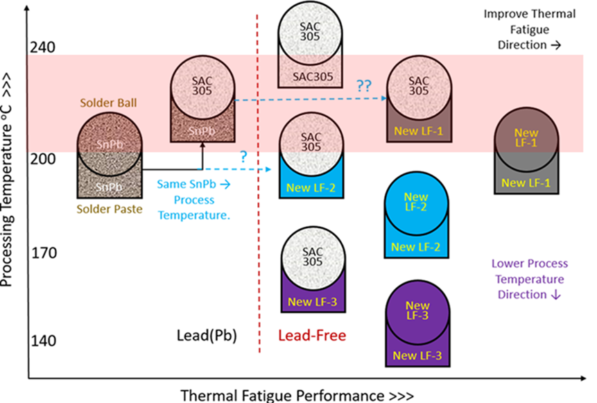
SnPb (tin/lead) is considered the most reliable solder alloy for aerospace/defense (IPC Class 3) applications because of its ability to withstand shock and vibration and mitigate Sn whiskering. SnPb components, however, are becoming obsolete from increasing restrictions of Pb in commercial applications. Presently waived for AD, these solders are increasingly expensive, with increasing supply constraints and reliability limitations. Moreover, current SAC 305 alloys also fall short of commercial performance objectives, especially in automotive (electric vehicle) end-use environments. As a result, the Raytheon Lead to Lead-Free (L-LF) team evaluated two current baselines and seven next-generation LF solder paste alloys based on three major “pathfinder” studies on representative SMT assembled test samples, to identify the best LF alloys for the next phase for production prototypes. An L-LF working subgroup was formed to outline a path forward to better anticipate and prepare the transition to a “pure” LF metallurgical system for circuit card assemblies (CCA). Raytheon has been successfully mixing SnPb paste and LF SAC 305 parts with ~225°C processing temperatures without having to reball from SnPb to Pb-free; this is ~15% of product today. The strategy is to transition from SnPb to next-generation Pb-free solder paste alloys to mix-assemble with SAC 305 or Sn surfaces between 200° and 240°C or melting ranges between 183° and 220°C for minimum transition disruption, but not too low; e.g., low-temp (~150°C) solders (LTS) that risk reflowing material with lower temperature processing used in subsequent next higher assemblies (NHA) (FIGURE 1).
Real-time X-ray Thermal Analysis
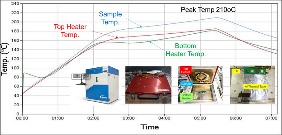
The heated or “hot-stage” stage installed on the current radiographic transmissive x-ray machine was used for real-time radiographic analysis as part of the evaluation of the next generation Pb-free solder pastes. The hot-stage permits emulation of thermal environments such as SMT reflow profiles to capture real-time x-ray video images as a function of time and temperature of materials and devices. Test PCB/samples were printed with baseline and candidate LF solder pastes to then transfer to the x-ray machine hot-stage for thermal x-ray analysis. The test PCB/samples are suspended centrally on guides between the top and bottom heating elements, which are both programmed for specific temperature ramp rates, dwell times and reflow processing times (FIGURE 2). The temperature of the sample is recorded from a thermocouple attached to or near the area of interest.
Test Sample Fabrication
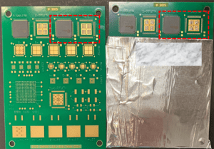
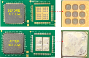
Samples were fabricated on 108 x 78 x 1mm PCBs for the solder paste under the device as well as the solder paste by itself to then be x-ray-viewed simultaneously or next to each other in real time during simulated SMT reflow. Each paste type was printed with 9 x 9 solder paste deposit pattern dots on each of the pad quadrants per MLF-100 thermal pad. Two pads had dummy 10 x 10mm MLF100 components placed, and two pads were left alone, with only the solder paste printed (FIGURE 3).
X-ray Analysis Thermal Profiles
FIGURE 4 shows SnPb solder paste snapshot x-ray images at different times during simulated SMT reflow on MLF-100 devices. The sample is hotter because the top and bottom heaters both contribute heat to the sample in between.
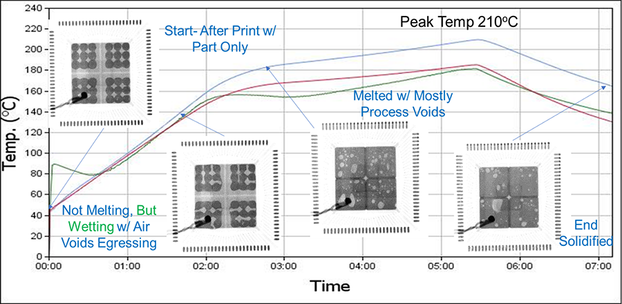
FIGURE 5a shows the LF-B solder paste snapshot x-ray images at different times during simulated SMT reflow on MLF-100 devices.
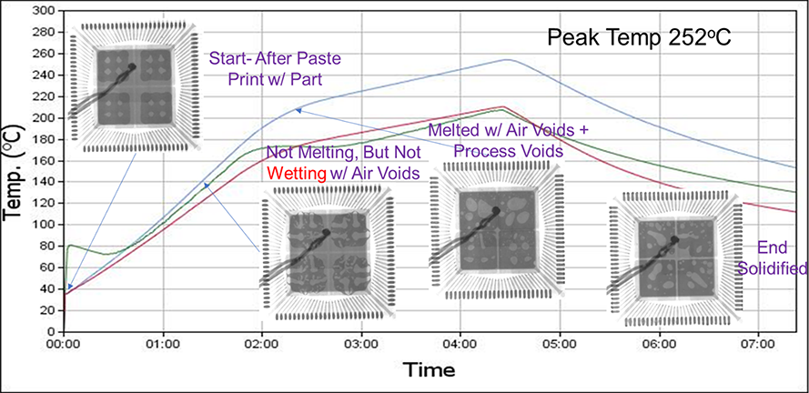
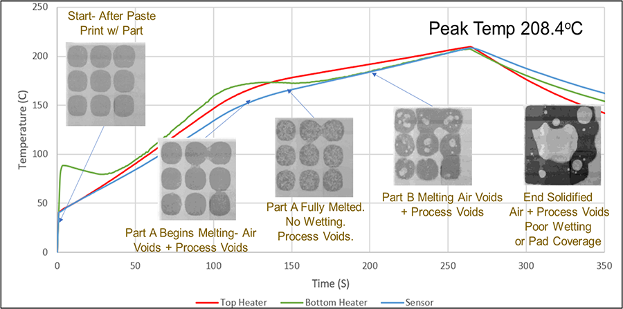
FIGURE 5b shows the LF-C solder paste closeup snapshot x-ray images at different times during simulated SMT reflow on one of four thermal pad quadrants of a MLF-100 device using two separate solder paste compositions.
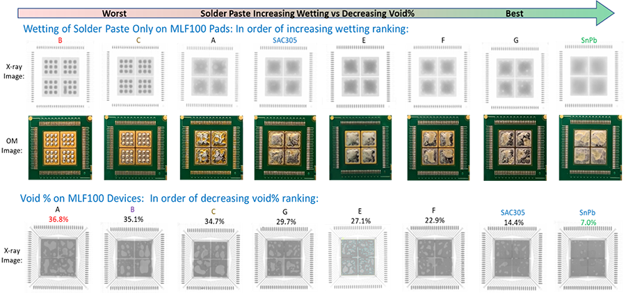
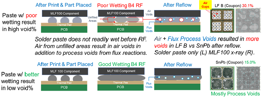
Solder paste wetting vs. void percentage results. FIGURE 6 shows solder paste-only printed on MLF-100 thermal pads without the device attached (x-ray top and optical microscopy center). Solder pastes that wetted better resulted in less void percentage under MLF-100 device thermal pad regions, as shown in x-ray images after SMT reflow on hot-stage (bottom).
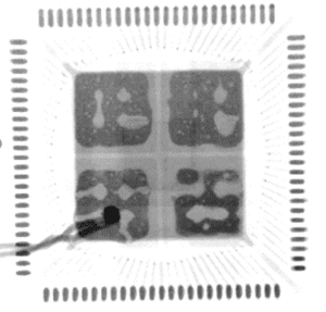
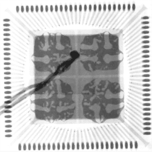
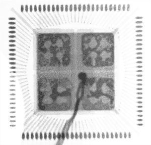
Void formation mechanism. SnPb, LF-B and LF-C solder pastes showed different amounts of air voids and process voids forming just before reflow or melting (FIGURE 7). The solder pastes with better wetting before melting were shown to more readily flow and move and permit the air voids to more easily escape or egress through solder paste. By comparison, solder pastes that exhibited poor wetting did not readily move and prevent air voids from escaping (FIGURE 8).
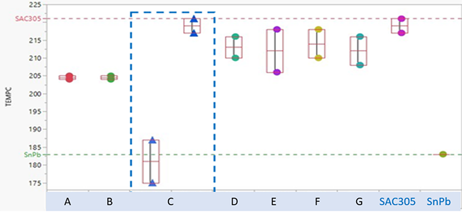
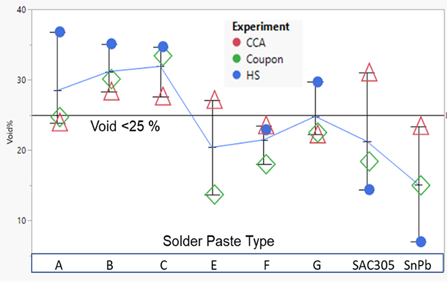
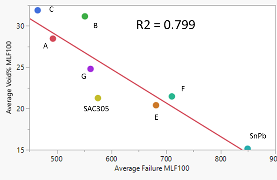
Solder paste void percentage vs. shock performance: All solder pastes. All three radiographic studies after actual SMT reflow; circuit card assembly (CCA), coupon and after SMT reflow on x-ray hot-stage for each solder paste are shown in FIGURE 9 (top). LF solder pastes A, B and C with >25 void% are compared to LF solder pastes E, F, G and SAC 305 with <25 void%. (A 25% void density is considered a maximum “guideline” by commercial industry.) A strong statistical correlation was observed between void percentage and shock performance, as shown in the plot at the bottom.
Summary
The hot-stage was successfully used to visually analyze the thermal effects on solder paste on CCAs using radiographic imaging in real time during SMT thermal reflow. For the L-Lead (Pb) to LF-Lead-Free Solder Paste pathfinder program, the tool was invaluable to evaluate the solder formation processes of next-generation lead-free solder pastes. After SMT-simulated x-ray hot-stage reflow, the solder pastes with higher void percentage correlated with solder pastes that exhibited less wetting or coverage. It was radiographically demonstrated that solder pastes with low wetting and higher void percentage resulted in a combination of entrapped air voids and process voids from typical flux reactions. Moreover, a strong statistical correlation observed between low void density and high shock performance provided quantitative data that helped determine which LF solder paste alloys to pursue for production. ![]()
Acknowledgments
Mojan John; George Georgacopoulos; Christine Carlucci; Alec Labitt; Michael Jansen; Erin Baker; Greg Beninati; Jeff Shubrooks; Anthony Rafanelli, Ph.D.; Dave Pinsky; Jim Faoro; and Karen Ebner.
References
1. Mohan John, RTX internal memo, RTX X-ray Hot Stage Quick Start Guide, May 1, 2022.
2. N. Armendariz, “Effect of QFN I/O Pad Solder Paste Overprint on Thermal Pad Void Reduction,” Proceedings of IPC Apex Expo, February 2020.
3. C. Nash and R. Lasky, Printed Circuit Assembler’s Guide to … Solder Defects, I-007e Books, 2021.
4. M. Jansen, A. Sciarratta, N. Casilli, and C. Boucher, “Nordson Dage Quadra 7 Void Analysis and Heated Stage,” 2020.
*This article does not contain technology or technical data controlled under either the US International Traffic in Arms Regulations or the US Export Administration Regulations.
Ed: This article is adapted from a paper of the same title first presented at the IPC Apex Expo Technical Conference in January 2023, with original work published within conference proceedings.
Norman Armendariz is an Engineering Fellow at Raytheon Technologies (raytheon.com) responsible for materials engineering design, materials analysis, process equipment development, production support and technology roadmaps associated with the manufacturing of circuit card assemblies used in missiles, smart munitions, ground-based radars, and mobile sensors across multiple US and international sites. He has over 25 years of industrial experience, having worked for LTV, Lockheed/NASA, Motorola, Intel, Texas Instruments and American University. He holds an interdisciplinary doctoral degree in chemical engineering from New Mexico State University, a master’s in materials science engineering from the University of Illinois, and bachelor’s in metallurgical engineering from Colorado State University, with nine US patents and 29 peer-reviewed publications.