Tear Resistance in Flexible Circuits
Proper design and handling can minimize the risk of rips.
I have a potential new application for a flexible circuit for use in an inspection device. The flexible circuit will see some light pulling and tugging forces when extracted. Should I be concerned the circuit may be prone to tearing? If so, are there different materials that can be used that will not tear?
The short answer is yes; flex circuits can tear if not properly designed or handled. You did not mention the number of layers or the thickness, so I will assume that your application is only one or two layers and is on the thin side. As the layer count goes up, so does the thickness, and therefore the strength and tear resistance. Once a flex is four-plus layers with standard thickness materials, it should be very durable, and tearing should not be a concern if the extraction does not generate extreme shearing forces.
Virtually all flex circuits use polyimide film as the primary insulator. Polyimide film has lots of great electrical and mechanical qualities, but tear resistance is not one of them. In static applications there is seldom an issue, but if there are multiple flexing cycles during service, preemptive steps mut be taken in the design to guard against tears. The key is ensuring that a tear does not start, because once it does, it tends to propagate.
How do you accomplish this?
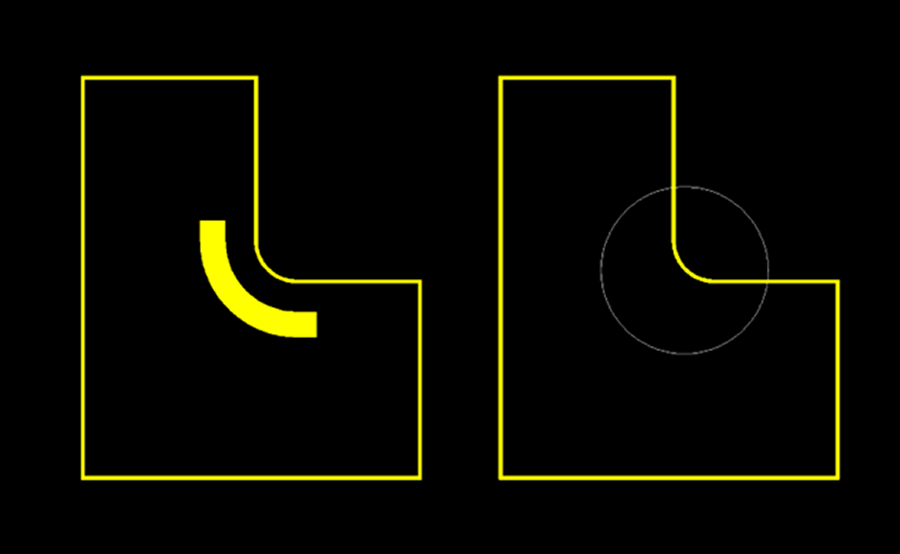
- Inside corners on the circuit outline are the most common areas for a tear to start. Inside corners should always be radiused, period. The larger the radius, the better! If a large radius is not possible, look at adding a laminated patch of flexible tear-resistant material that will cover the sharp radius. This patch is applied before the parts are punched out of the panel, so the patch would follow the exact contour of the circuit edge and would then extend inward ~0.125″ or more. Some examples of flexible, tear-resistant materials are PTFE or similar film that stretch rather than tear. Tyvek (the stuff they use to make full body biohazard suits) is also a good choice because it is inexpensive, flexible and virtually impossible to tear. The downside is it must be applied after any SMT operations; I don’t believe it would hold up in a reflow oven.
FYI, etched copper “tear stops” are not an effective way to keep a tear from propagating unless the copper is really thick (2oz+). Since most flex circuits are made with 1oz copper or less, a tear in the polyimide will run through the copper “tear stop” as if it weren’t even there (Figure 1).

- Slits that go into the flex to separate different flex legs require a relief hole at the end of the slit. A slit is, after all, a partial tear. The relief hole at the end of the slit should be as large as possible (within reason). If flexibility beyond the end of the slit is not required, try laminate stiffeners to get the slit from propagating further into the circuit that you intended.
- Sharp edges along a stiffener can be an issue if there will be shearing forces in the application. This is typically an issue only in instances of one or two layers of flex. The standard “fix” is to apply a bead of semirigid epoxy along the stiffener edge. This is effective only if the stiffener is thick enough (over ~0.020″) for the applied bead to have a roughly triangular cross-section. If the stiffener is very thin, the cross-sectional shape will be more like a half-moon and will have limited effectiveness.
- Ensure the flex supplier uses a final punching tool that will leave a smooth profile without any nicks or cuts that could start to run through the rest of the circuit.
- Ensure operators use caution when installing the circuits so that they do not cause damage to the circuit profile.
- When the circuit is installed, it should be relaxed and not under any tension that could cause a tear to start and propagate.
- Using thicker layers of polyimide for the base laminate and outer cover material can make the circuit more robust, but the downside is that the circuit will be stiffer due to the added thickness, which may or may not be acceptable in the application.
I always recommend to contact the flex circuit supplier if the application has any special features that could cause undue stress on the circuit materials. Examples of this are a sharp twist in the flex when installed, odd profiles like serpentine patterns, or as in the application described at the start of this column, the need to pull on the flex to uninstall. Every application is unique and flex suppliers have probably seen it before and can steer you in the right direction.
Mark Finstad is director of engineering at Flexible Circuit Technologies (flexiblecircuit.com); mark.finstad@flexiblecircuit.com. He and co-“Flexpert” Nick Koop (nick.koop@ttmtech.com) welcome your suggestions. They will speak at PCB West at the Santa Clara Convention Center in October.


