


Via Viability
Flex and rigid-flex can handle all via types – with some considerations.
We have talked before about vias, but some situations can trip you up in flex and rigid-flex, and some tricks can be exploited to overcome them. When it comes to rigid-flex and flex, keep in mind these things.
To start – yes, you can put a microvia in a flex laminate. In fact, I would argue that in an apples-to-apples comparison, a microvia in flex laminate will be more reliable than in rigid reinforced laminate. There are a few reasons for this. One is, the thin flex cores enable low aspect ratio vias, which has been proven to improve reliability.
Flex microvias can also take advantage of certain material attributes. Because flex laminate is a homogenous film without any reinforcement, it lasers very cleanly and the side walls of the hole are uniform. Without any glass weave, the laser cuts through the dielectric evenly, reaching the target pad at the same time with the same power level across the pad. This results in a consistent target pad surface for plating.
Another advantage of flex microvias is the modulus of the material. Polyimide film has a CTE of 25 when below the Tg, but when above the Tg, its CTE is only 40. Moreover, its modulus is 700kpsi. Rigid laminates tend to have lower CTE in the X and Y axes, but much higher CTE in the Z. This is due to the glass weave constraining the X and Y axes. Likewise, the rigid laminates have higher modulus values; often four times higher.
What does this mean? When it comes to microvia failures, it is primarily about thermally induced stress, with expansion causing strain on the via – sometimes to failure. What is interesting about the polyimide film is that since there is no reinforcing weave, CTE and modulus are omnidirectional. Thus, while rigid laminate will force most of the stress in the Z, flex laminate will distribute in all three directions. Moreover, the lower modulus in flex means the copper via will be stronger than the film and thus drive more of the CTE into the XY and less into the Z.
I like to think about the physics formula of PV=nRT. As the temperature rises, the volume of the board wants to increase. In rigid, the expansion will be almost all in the Z axis, while in flex it will preferentially be in the X and Y, so less stress on the via results in very reliable microvias in flex laminates.
Another consideration is when flex involves buried vias.
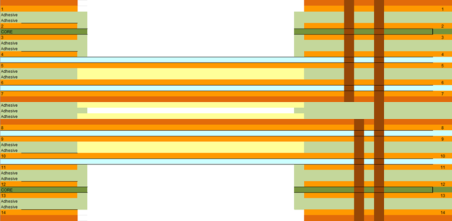
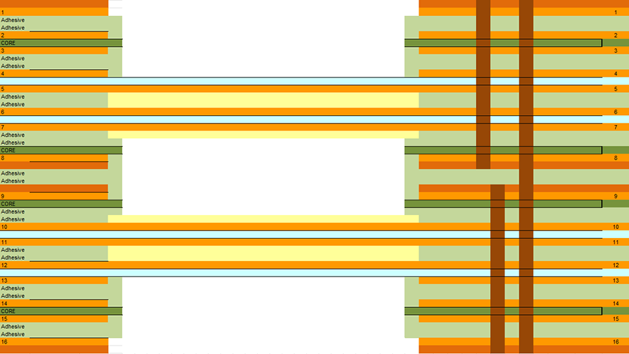
If we are putting a buried via in the flex structure (two or more layers), we need to think about how we might fill the vias. To begin, the standard epoxy via fill process is generally not a viable option with flex layers. The biggest concern is that the required planarization operation after cure will damage the flex layers. It is hard to hold the flex perfectly flat and remove the resin without sanding too deep. All is not lost, however; we have strategies for this. For pure flex sub-laminations, we can often just permit the prepreg resin to fill the vias in the next lamination cycle. These flex subs are usually very thin and will easily be filled by the prepreg resin without consuming excessive resin.
In other cases, we may have a sublam that is a combination of rigid and flex, typically as a blind via where the top is rigid and the bottom is flex. Again, there is risk of damage to the bottom flex side during planarization. In these cases, we recommend adding a rigid cap layer on the flex layer – creating an internal rigid pad layer when final lamination is completed. This allows us to protect the flex through the planarization step. You can rearrange the rigid and flex laminates within the sub such that the flex is sandwiched between rigid layers, keeping it protected.
Do you need backdrills to manage stubs? Rigid-flex permits it, but keep in mind that flex cores are thinner than rigid ones. As a result, a backdrill cannot end within a flex core as they are too thin. After backdrilling, the plated via stub may extend at least one extra pad layer between the cut layer and must-not-cut layer. Depth tolerance is essentially the same whether rigid or rigid-flex, however.
Another consideration is a two-layer flex with microvias. This may be a pure flex or a flex “tail” on a rigid-flex. If microvias are needed in this flex, consider from which side the microvia is formed. If the microvias are formed on the side opposite the SMT components, there is no need to copper fill the microvias as the opposite side is already flat – it is the undisturbed copper foil. This can help manage costs.
Another advantage with microvias in flex laminates is that the absence of glass weave means no opportunity for CAF (conductive anodic filament). This can be more significant as the pitch between vias gets tighter.
The takeaway here is that rigid-flex (and flex) are fair game for all via types. There are a few considerations to keep in mind, but you can be successful. If you are unsure how to navigate, pick up the phone and make a call to be certain.
Nick Koop is director of flex technology at TTM Technologies (ttm.com), vice chairman of the IPC Flexible Circuits Committee and co-chair of the IPC-6013 Qualification and Performance Specification for Flexible Printed Boards Subcommittee; nick.koop@ttmtech.com. He and co-“Flexpert” Mark Finstad (mark.finstad@flexiblecircuit.com) welcome your suggestions. They are speaking at PCB West at the Santa Clara (CA) Convention Center in October.