

Permittivity vs Permeability: What’s the Difference?
Some areas of physics have considerable impact on PCB designs.
by Douglas Brooks, Ph.D.
PCB designers have had exposure to electronics (some more than others). And most of what we do falls under the field of electronics. But designers often have little or no exposure to physics. And some areas of physics have considerable impact on our designs. Here we look at two physical properties of the dielectrics we work with, and why they are important to understand (Note 1).
Permittivity. Why are some capacitors able to store much more charge than others? What is the relative dielectric coefficient associated with dielectrics and why does it matter? The answer relates to a property called permittivity. Before we get too far into this topic, we need to clarify some terms.
Dielectric constant is an out-of-date term that means the same as permittivity, εm. The permittivity of a vacuum, ε0, is given as 8.85418782 x 10¹² Farads/meter. The relative dielectric constant, εr, or relative permittivity, is the ratio of the material permittivity to the permittivity in a vacuum, or
εr = εm / ε0
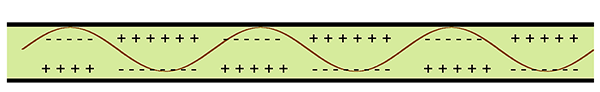
εr is the variable we are familiar with that impacts such things as controlled impedance and signal propagation speed. It is a measure of the electrical polarization that can occur in a material in response to an applied charge, or voltage, across the material. FIGURE 1 illustrates a board with a differential pair of traces on either surface (or it could be a trace over a plane). The waveform illustrates a snapshot of a signal propagating along the trace from left to right. Prior to any signal, all electrical charges are distributed randomly throughout the material. When the signal polarity is one direction, the atoms and molecules in the dielectric are pulled in one direction (by Coulomb’s Law, opposite charges attract). As the signal changes polarity, the atoms and molecules are pulled in the opposite direction. This action tends to electrically polarize the material.
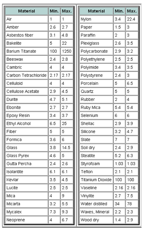
Materials with high relative permittivity polarize to a greater extent. That means they can store more charge. If such material is between the plates of a capacitor, that means the capacitance increases. figure 2 provides relative permittivity values for several materials. Materials typically used in capacitors have relatively high relative permittivities (tantalum ≈ 25, ceramics ≈ 38).
The physics of realigning the charges in a dielectric as a signal passes by takes energy. This energy is lost to the signal as it passes by. In one form, the losses manifest themselves as dielectric losses. Dielectric losses are a function of frequency (they increase as the frequency increases) and of temperature. One practical consequence of dielectric losses is that the characteristic impedance of the trace changes. This means there is no longer a single resistor value that can effectively terminate the trace (Note 2). And this means that signal reflections may become an issue.
Higher permittivities in dielectrics increase the capacitance between the trace and underlying planes. Therefore, dielectrics with higher permittivities will lead to lower characteristic impedances for traces, affecting controlled impedance calculations. And since realigning charges absorbs energy from the signal, the signals will slow down in dielectrics with higher permittivities.
So, from an electronic standpoint, the capacitance of a capacitor or a trace is determined by the area of the plates and the distance between them. But the physics of the material between the plates can have a dominating effect on that capacitance.
Note that permittivity relates to charged particles (electrons) and their inherent charge. This will contrast with permeability, below.
Permeability. In electromagnetism, permeability is the measure of magnetization that a material obtains in response to an applied magnetic field. (Compare with permittivity, above.) Permeability is typically represented by the (italicized) Greek letter mu, or μ. In the macroscopic formulation of electromagnetism, there appears two different kinds of magnetic field:
• The magnetizing field H, which is generated around electric currents and also emanates from the poles of magnets. The SI units of H are amperes/meter.
• The magnetic flux density B which acts back on the electrical domain, by curving the motion of charges and causing electromagnetic induction (Note 3). The SI units of B are volt-seconds/square meter (teslas).
Relative permeability, denoted by the symbol uT, is the ratio of the permeability of a specific medium to the permeability of free space:
μ0: uT = u/u0
where u0 = 4π × 10-7H/m is the magnetic permeability of free space.
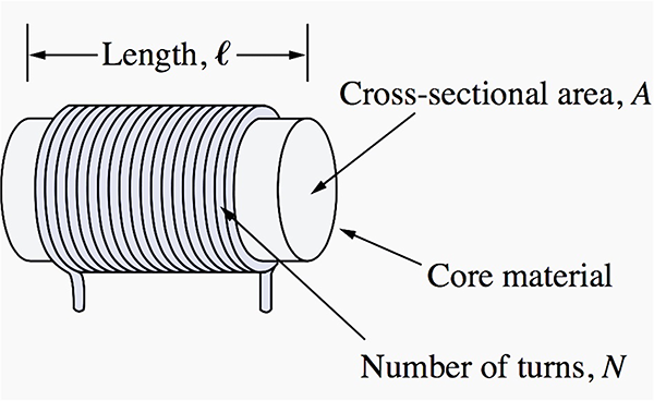
The importance of permeability is that it “amplifies” the magnetic field created by a current. For example, if we form a current-carrying conductor into a coil, as shown in FIGURE 3, a magnetic (H) field will be generated inside the conductor loops. This will cause inductance in the conductor, the magnitude of which depends on the geometry of, and number of, the turns. If the core material inside the loops is air, the inductance will be relatively small. But if the core material has a high permeability (say an iron core) the magnetic field will be much larger, generating a much larger inductance in the coil.
So, from an electronic standpoint, the magnitude of the inductance depends on the geometry of the coil. But the physics of the material inside that loop can have a dominating effect on that inductance.
In terms of permeability, there are three types of materials: diamagnetic, paramagnetic and ferromagnetic. Ferromagnetic materials are the only ones that significantly focus the magnetic field around a conductor. Circuit designers generally are only interested in ferromagnetic materials. Only four common elements are ferromagnetic: Fe (iron), Co (cobalt), Ni (nickel), and Gd (gadolinium, look it up!).
The root cause of permeability is electron spin (as opposed to electron charge creating permittivity). A current through a wire generates a magnetic field around the wire (Faraday’s law). Electron spin creates a magnetic moment at the atomic level. In general, electron spin is chaotic and random for most materials. But the tendency (ability) of many of the electrons to align their spin in the same orientation is the characteristic that creates magnetic permeability. In some materials this orientation is only temporary and dissipates when the external magnetic field is removed. But with certain materials, and under certain conditions, a material can become permanently magnetized. 
References
1. Aaron Thomas – Electromagnetics blog, “Relative Permittivity – Beeswax/Teflon Interface,” https://sites.google.com/site/atspring2013/refraction—2009/relative-permittivity—beeswax-teflon-interface.
Notes
1. This article is adapted from Brooks’ new book, Physics of Electronics for PCB Designers, available for free download at ultracad.com.
2. Doug Brooks, “UltraCAD’s Best Articles and Application Notes,” Chapter 17, 2022 (available on Amazon.com).
3. When we apply a changing current through a wire, the magnetic field it creates is the H field. That field creates a current in the opposite direction (causing inductance and skin effect. Again, see Note 2, Section 1.b). The induced magnetic field caused by the new induced current in the backwards direction is the B field.
Douglas Brooks, Ph.D., has bachelor’s and master’s degrees in electrical engineering from Stanford and a Ph.D. from the University of Washington. He owned an engineering service firm and has published multiple books, including Physics of Electronics for PCB Designers and PCB Design Guide to Via and Trace Currents and Temperatures; doug@ultracad.com.