

Basics of High-Frequency PCB Materials
An overview of the physical and electrical characteristics of rigid and flex laminates.
by Sagi Balter, Ph.D. and Vitaly Bensman
Electronic devices functioning at high frequencies are currently evolving at a dizzying pace, particularly within the field of wireless communication. When developing new products, therefore, emphasis is placed on utilization of materials suitable for high-frequency work, above 1GHz.
When selecting materials intended for high-frequency printed circuit boards, several characteristics are of importance:
- Dielectric constant (Dk) – dielectric coefficient of the resin. This parameter must be low and stable within a wide range of high frequencies. High Dk values may decelerate signal transfer speed.
- Dissipation factor (Df) – the parameter responsible for the signal’s quality. The Df value should be low. The lower this value, the more stable the signal, and losses will be reduced.
- Moisture absorption – another imperative parameter when selecting materials intended for high frequencies. This is important because the Dk of water is Dk;water = 80.4, a value so high, in fact, the absorption of very small amounts of moisture will instigate a significant increase in the overall Dk of the material.
- Coefficient of thermal expansion (CTE) – thermal dimensional expansion parameter of the dielectric material. This parameter must be close to the CTE of the conductive metal; in the case of PCBs, it is copper. Working at high frequencies causes increased heating of the PCB and thus if a significant discrepancy exists between the CTE of the dielectric material and the copper, structure delamination may occur during the activation of heating/cooling cycles.
- Additional important parameters such as:
o Thermal resistance.
o Chemical resistance.
o The adhesion strength between copper and the dielectric material.
Traditionally, PCBs intended for high frequencies are designed or manufactured using polytetrafluoroethylene (PTFE)-based materials, known widely as Teflon. In fact, presently, a wide range of resin-based materials, such as epoxy-glass, are suitable for production of PCBs intended for diverse applications of high-frequency.
One of the common methods for improving the performance of non-PTFE-based materials (and that of PTFE-based materials as well) in high frequencies is to select a suitable type of copper, meaning the roughness profile.
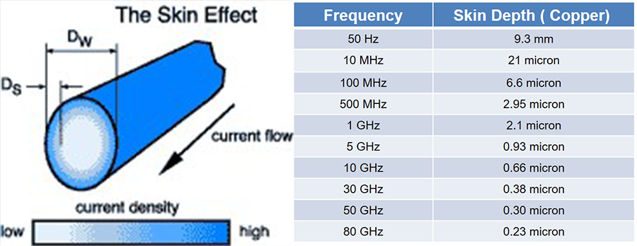
When working with high frequencies, an influential and significant phenomenon for signal transfer quality is called skin effect. As frequency increases, the electromagnetic field generated as a result of electron conduction in the conductive material influences the flow of the electric current in the conductor and “shoves” it closer to the outer skin.
The skin effect phenomenon intensifies the impedance and causes increased conduction losses as well as deceleration of signal transfer (Figure 1). Upon increase of the frequency, the skin depth (the skin’s thickness) is reduced.
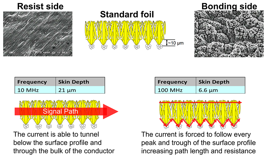
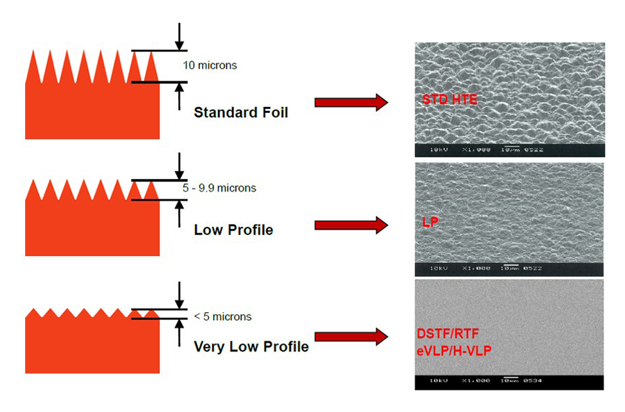
To reduce skin effect during production of copper-clad laminates (CCL) intended for high-frequency use, low-profile copper is used at the bonding side – the side adjacent to the dielectric resin (Figure 2). The main types of copper utilized in the production of CCLs are standard, low-profile and very low-profile.
To improve performance, low-profile copper with tooth size (roughness) less than 5µm is preferred (Figure 3). Nonetheless, if using this type of copper foil combined with PTFE, which is known to have low adhesion strength, consider that the likelihood of delamination between the copper and PTFE in the diverse production processes, as well as thermal shock, is very high. This point is precisely when thermoset materials (such as epoxy-glass), which possess a high adhesion strength to copper, gain an advantage over PTFE.
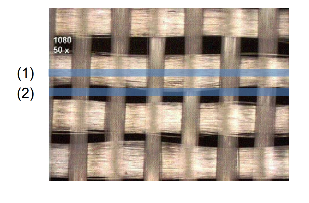
In addition to the copper type, meaning the roughness characteristic, another parameter contributes to the stability of signal transfer in a PCB. The dielectric base of CCL exhibits a nonhomogeneous and anisotropic structure in terms of Dk values.
In general, the Dk values for resin and glass fibers are not identical: Dk resin < Dk glass fiber.
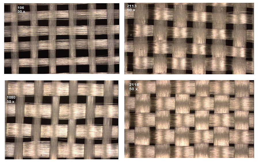
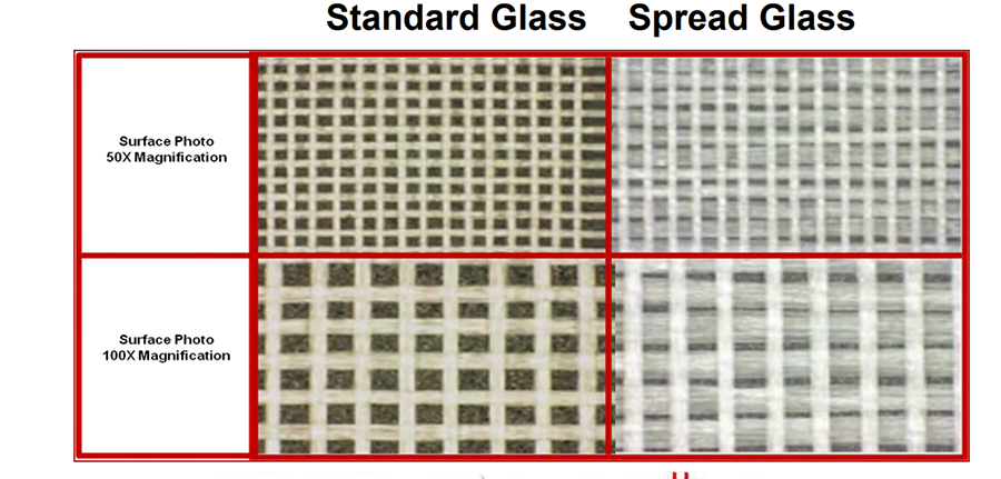
A conductor that will traverse over a fiber bundle (1) and a conductor that will traverse over a resin-saturated area (2) will exhibit a different Dk (Figure 4). The solution proposed for this phenomenon is the utilization of a more homogenous glass fabric, such as 2116 or 3113, instead of 1080 or 106, or the use of flattened glass fibers, such as spread glass, which enables the production of a more homogenous dielectric material (Figure 5).
Naturally, the PTFE resin occupies a prominent place in a very broad variety of raw materials designated for PCB production. Presently, companies that produce PTFE-based CCLs offer varied solutions for improving the electrical performance of these materials; for instance: improving dimensional stability through use of glass fiber fabrics or other hardening materials; utilizing ceramic fillers for controlling the Dk or Df values. Another advantage of PTFE is its very low moisture absorption level and high resistance in aggressive work environments.
On the other hand, PTFE has significant disadvantages in the production processes of PCBs: high cost; low copper adhesion strength; significant difficulties in the preparation of surfaces for copper plating in holes and lamination with other materials. In most cases, use of PTFE-based CCLs requires PCB manufacturers to use multiple expensive, complex and aggressive processes, which raise the price of the final product and influence yield of Teflon-based PCBs.
In work frequencies ranging above 10GHz, Teflon-based raw materials have very few competitors, nonetheless, a range of alternative glass epoxy-based materials are available in frequency ranges of 1 to 5GHz, such as PPO (polyphenylene oxide) or PPE (polyphenylene ether) as well as diverse polymer mixtures.
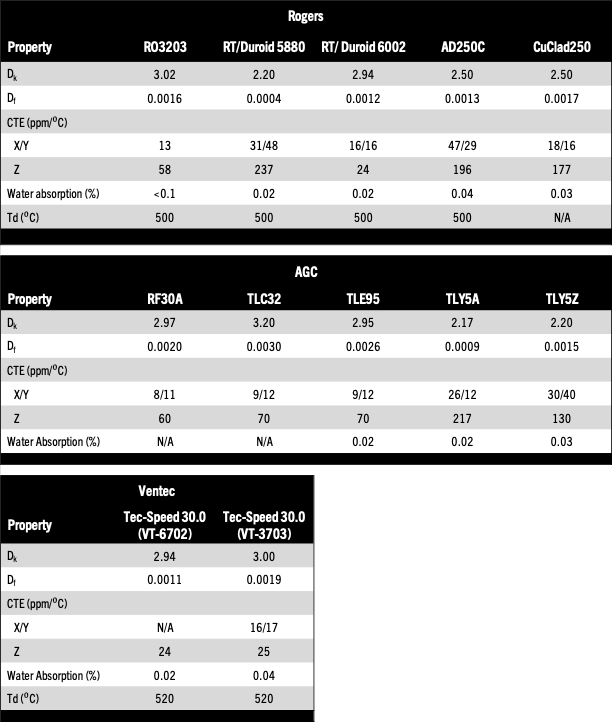
Currently many companies manufacture CCLs intended for high frequencies. For Teflon-based laminates, they include (but are not limited to):
- Rogers – with the following series of materials – RO3000, RT/Duroid and CuClad series as well as several additional types.
- AGC (Taconic) – with the TLY, TLC and RF series of materials, and a few others.
- Ventec – with the Tec-Speed 30.0 series of materials (a relatively new material on the market).
Some technical data for PTFE materials are shown in Table 1.
For laminates based on non-Teflon materials, several companies also supply products, including but not limited to:
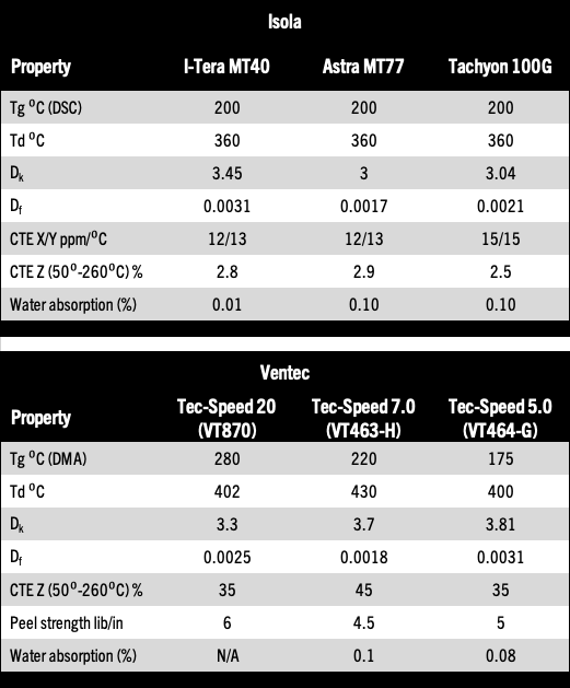
- Isola – with materials such as I-Tera MT40, Astra MT77, Tachyon 100G.
- Ventec – with the Tec-Speed series of materials.
Some technical data for non-Teflon materials are shown in Table 2.
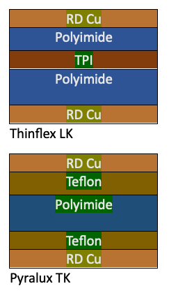
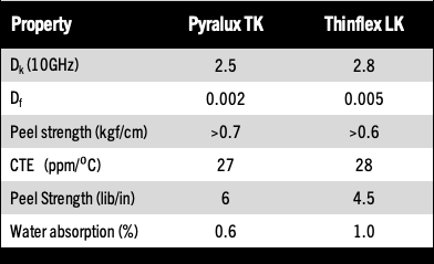
In addition to rigid materials, special flexible materials are utilized for production of flexible/rigid (rigid-flex) PCBs intended for high-frequency use. In fact, in the field of flexible materials for high frequencies, as of today, the materials available are modest compared with rigid versions. Presently, only two companies provide flexible materials intended for high-frequency use: DuPont with its Pyralux TK material, and Thinflex with its Thinflex LK material.
Pyralux TK is an adhesive material that uses Teflon-based adhesive for bonding the flexible base polyimide (Kapton) and the copper foil layers. As a result of the use of Teflon-based adhesive, this flexible material is characterized by advantages and disadvantages similar to Teflon-based rigid materials.
Thinflex LK is an adhesiveless material made of a polyimide base layer and copper foil on both sides. The production processes of PCBs with a Thinflex LK layer are identical to production processes using standard flexible materials.
Technical data that characterize Pyralux TK and Thinflex LK are shown in Table 3.
In conclusion, in our experience the most suitable materials for conventional and standard production processes are epoxy glass-based thermoset materials and non-Teflon materials that are adapted for use in high-frequency ranges. As opposed to Teflon-based materials, thermoset materials can be used for building a variety of rigid, rigid-flex and HDI (high-density interconnect) PCBs. It is impossible to ignore that the most efficient materials for high-frequency performance that are suitable for a wide range of frequencies are Teflon-based materials, yet these materials pose numerous fabrication challenges, the cost of this type of product is very high, and its production time is significantly longer compared with the other materials. 
References
1. Isola, “PCB Material Selection for High-Speed Digital Designs,” company presentation, https://www.isola-group.com/wp-content/uploads/PCB-Material-Selection-for-High-speed-Digital-Designs-1.pdf.
2. Isola, “Understanding Glass Fabric,” company presentation, https://www.isola-group.com/resource/understanding-glass-fabric/.
Sagi Balter, Ph.D., is chief technology officer and Vitaly Bensman is senior process engineer at Eltek (nisteceltek.com); sagib@nisteceltek.com.